
Data Format TAFFmat
The recorded data file format for the TEAC data recorders adopts TAFFmat (TEAC Data Acquisition File Format). This is a file format that allows recorded data files to be read directly from PC applications.
Type of files
WX-7000 / LX-1000 / es8 makes a binary-format data file and ASCII-format header file each time recording stops or pauses.
| File type | Format |
|---|---|
| Data file | Contains data converted from analog to digital, etc. (binary format with "dat" file extension) |
| Header file | Contains recording conditions and other information Text (ASCII) format with "hdr" file extension |
| Voice memo file* | Contains voice memo data WAV format with "wav" file extension |
| GPS file* | Contains GPS data "gps" file extension |
| Index file | Contains recording conditions and other information Text (ASCII) format with "hdx" file extension |
File name
The file name is common to the data file and header file. An ID number is added to the end of the specified file name. When you specify a new file name, the ID number starts from 1. After recording is stopped or paused, the ID number is automatically incremented each time the recording restarts. If a data file with the same name or same ID number already exists when recording, the next ID number is used.
Set the file name on the LXK Navi File Settings Screen or the RECORDING FILE Settings Screen of the remote control unit (optional). For the file name, use up to 29 half-width alphanumeric characters. ID numbers (starting from 001) with the set number of digits are attached to file names.
When recording to an SD card, the number of digits is fixed to 3, and the maximum number of characters is 32. When recording to a computer, the number of digits can be set from 3 to 5, and the maximum number of characters is 32–34.
- If the ID number exceeds the set number of digits, recording will stop.
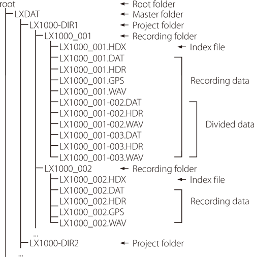
Media folder structures (e.g.LX-1000)
| Folder type | Name | Details |
|---|---|---|
| Master folder | LXDAT | This is created in the root folder. Data is managed inside it. The name is fixed. |
| Project folders | Characters as set (Example:LX1000-DIR1) |
These are created in the master folder. Their names can be set as desired. |
| Recording folders | Characters as set (Example:LX1000_) |
These are created in project folders. Their names can be set as desired. Each time recording starts, a recording folder is created with a 3-digit suffix added automatically. |
| Recording data | Same as recording folder | When a recording is divided at 4 GB, a -followed by a three-digit suffix will be added to the name |
Folder structure example
Data file
16-bit data converted from analog to digital is recorded as 2-byte integer values from -32768 to +32767 while 24-bit converted data is recorded as 4-byte integer values from -8388608 to +8388607. Negative numbers are shown using two's-complement notation.
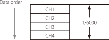
The byte order is from the lowest to the highest (Intel format).The data order is from the first sampling channel to the second sampling channel and so on until the last sampling channel. This order is called the INTERLACED format, and the format name is recorded in STORAGE_MODE in the header file.
The structure of a data file is as follows. In this document, a collection of data as shown in the example is called a "scan". A data file is made of repeated scans.
Example of data for one scan recorded at 6kHz sampling frequency
Converting data to physical quantities
16-bit data converted from analog to digital is recorded as integer values from -32768 to +32767 and the value wouldbe ±25000 when the input is ±100% in the input range settings. 24-bit converted data is recorded as integer valuesfrom -8388608 to +8388607 and the value would be ±6400000 when the input is ±100% in the input range settings.
The input value is obtained from the following formula:
Input value = (A/D conversion value of the data file) × SLOPE + Y_OFFSET
- See "Explanations of header file" on page 8 for information about SLOPE and Y_OFFSET.
Header file
Header files are ASCII-format text files containing information such as recording conditions.In a header file, each recording-condition entry is written on 1 line, with parameters separated by a comma (,). An example of a header file is shown as follows.
Example of header file

| DATASET | File name |
|---|---|
| VERSION | 1 (This is a fixed value.) |
| SERIES | Name of each channel |
| DATE | Date when recording started (month-day-year) |
| TIME | Time when recording started (hour: minute: second) |
| RATE | Sampling frequency (Unit: Hz) |
| VERT_UNITS | Physical units of each channel |
| HORZ_UNITS | Time axis units (Sec: This is a fixed value) |
| COMMENT | Comment input on the file settings screen |
| NUM_SERIES | Number of recording channels |
| STORAGE_MODE | Data order. Fixed as INTERLACED because this is the scan order. |
| FILE_TYPE | In 16 bits A/D, INTEGER (1data, 2-byte integers) In 24 bits A/D, LONG (1data, 4-byte integers) |
| SLOPE | Coefficient used when converting data to physical units |
| X_OFFSET | Location of the first data on the time axis; normally 0 The setting value (number of seconds to three decimal places) is written in minus for the pre-trigger time. Even if you set the number of scans for Pre-trigger, this will be in seconds. |
| Y_OFFSET | Offset used for converting data to physical units |
| NUM_SAMPS | Number of data items recorded per channel |
| DATA | The data that follows this entry is specific to this model, and it might differ from the formats of other models. |
| DEVICE | LX-1000 |
| SLOTn | Amplifier name and number of channels installed in SLOT n |
| CH1_ | The following information is written after the underscore: channel names and amplifier settings (input range, coupling, sensor current, weighting filter, HPF setting) for PA amplifiers, and output ranges and output channel settings for AO amplifiers |
| REC_MODE | Recording destination device (SD, PC, SD+PC) |
| END_TIME | Recording end time |
| START_TRIGGER | Recording start conditions COMMAND: Command DATE: Start time setting EXT: External trigger TIME_OUT: Timeout SYNC: Synchronized recording PRE: Added for a pre-trigger |
| STOP_CONDITION | Recording stop conditions COMMAND: Command LEVEL: Level trigger TIMER: Specified recording time EXT: External trigger MEDIA FULL: When media becomes full SYNC: Synchronized recording POST: Added for a post-trigger |
| START_PRE_COUNT | Number of scans recorded by a pre-trigger |
| STOP_POST_COUNT | Number of scans recorded by a post-trigger |
| MARK | Number of scans at the instant an event mark was attached. |
| VOICE_MEMO | The bits per sample and data size (bytes) for voice memos |
| LX-1000_VERSION | LX-1000 main firmware and FPGA versions and amplifier unit firmware and FPGA versions |
| DIVIDE | File division number (added when files are divided at 4GB intervals) |
| SYNC | Synchronized recording setting |
Utilization software for data after recording
TAFFmat (TEAC Data Acquisition Data File Format) is adopted for the recording data file format of the TEAC data recorders.
Software for LX-1000
| Product name | Description |
|---|---|
| T-Rec-X-Basic | T-RecX-Plus software bundle consists of three different software applications designed to get the best from your measured data. While T-RecX acts as a hardware connector and recording engine, RTA-VU2 allows real-time analysis and presentation in different ways. T-Mat, as the third, adds powerful analysis functions that meet even the highest demands and rounds off the package to a complete, full-featured measurement acquisition and analysis workbench. |
Measurement data waveform display software
| Product name | Description |
|---|---|
| TX-View | TAFFmat data viewer software recorded by the TEAC recorders |
| T-Mat | T-Mat is a customized TEAC Edition of EdasWin from MH: |
| Dadisp | DADiSP® is a software package from DSP Development Corporation. |
| FlexPro | FlexPro is a software package from Weisang GmbH. |